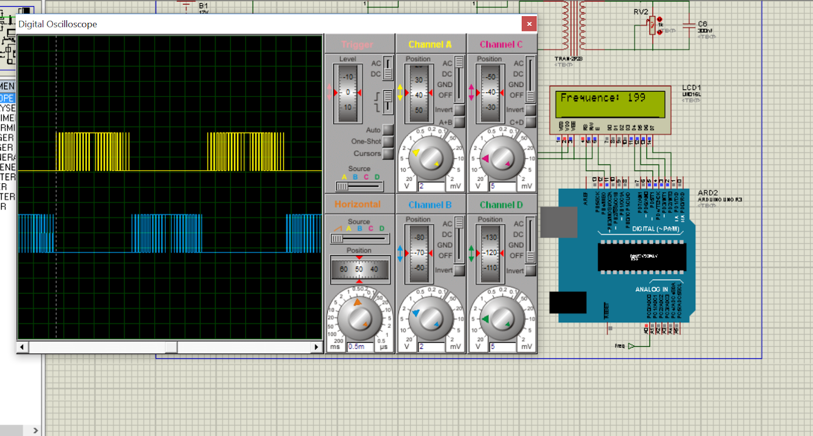
Hello my friends today I will show you my project the implementation of Sine PWM signal with variable frequency with Arduino and Proteus.
Introduction:
Pulse-width modulation (PWM), or pulse-duration modulation (PDM), is a
method of reducing the average power delivered by an electrical signal, by
effectively chopping it up into discrete parts. The average value of voltage
(and current) fed to the load is controlled by turning the switch between
supply and load on and off at a fast rate. The longer the switch is on compared
to the off periods, the higher the total power supplied to the load. Along with
maximum power point tracking (MPPT), it is one of the primary methods of
reducing the output of solar panels to that which can be utilized by a
battery.[1] PWM is particularly suited for running inertial loads such as
motors, which are not as easily affected by this discrete switching, because
they have inertia to react slow. The PWM switching frequency has to be high
enough not to affect the load, which is to say that the resultant waveform
perceived by the load must be as smooth as possible.
Brief
Theory:
A sinusoidal PWM (sPWM) signal can be constructed by dynamically
changing the duty- cycle. The result is short pulses at the zero-crossings and
long pulses at the wave peaks. This can be seen in the figure below.
Code
and Explanation:
In this chapter we'll step through the code found in the folder
sPWM_basic, and then the difference between it and the code found in the folder
sPWM_generate_lookup_table will be discussed. Code found in sPWM_atmel is for
use on an atmel chip without using the arduino IDE.The code toggles a pin for
every period of the sine output in order to make it osilliscope friendy.
sPWM_Basic:
The following C code implements an sPWM on a Atmel micro-controller. The
signal is generated on two pins, one responsible for the positive half of the
sine wave and the other pin the negative half. The sPWM is generated by running
an (ISR) every period of the PWM in order to dynamically change the duty-cycle.
This is done by changing the values in the registers OCR1A and OCR1B from
values in a look up table. There are two look up tables for each of the two
pins, lookUpTable1 and lookUpTable2 and both have 200 values. The first half of
lookUpTable1 has sin values from 0 to π and the second half is all zeroes. The
first half of lookUpTable2 is all zeroes and the second half has sin values
from 0 to π as shown in figure below.
Testing
the Signal:
This chapter discusses ways to test and monitor the sPWM signal, the
first section discusses using as oscilloscope which is the best method to
verify the signal however an alternate and cheaper method is to use a small
speaker. The 50hz signal and the underlying switching frequency is easy to
hear.
Viewing
Pulse Widths with an Oscilloscope:


No comments:
Post a Comment